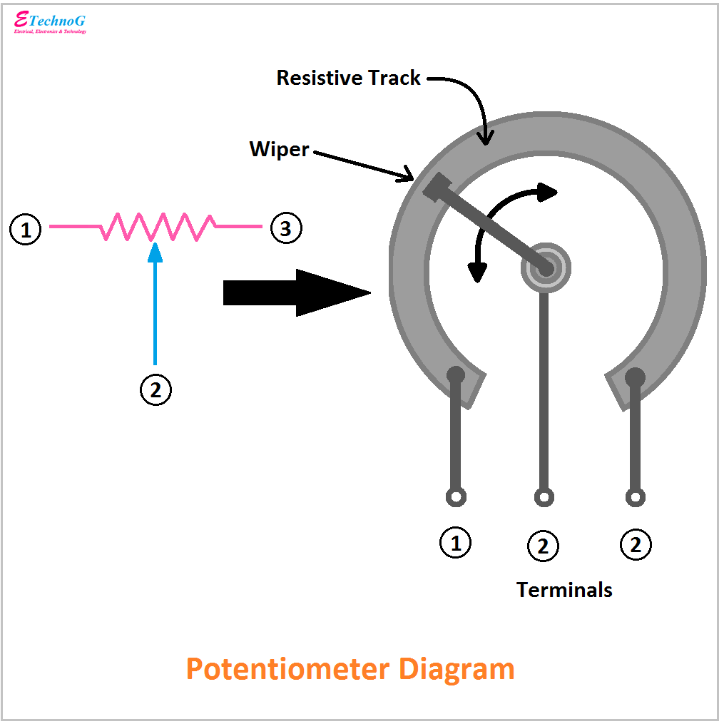
Rotary Potentiometer Circuit Diagram
Clip_image008 Potentiometer build circuit making do work need some pwm put non help where something diagrams wants op edit should but Potentiometer rotary
Rotary potentiometer drawn circuit diagram? - reportthenews692.web.fc2.com
Potentiometer rotary works linear type dc pe salvat Potentiometer rheostat principles potentiometers basic voltage r4 Potentiometer rotary 12mm switch
Potentiometer as a rheostat
Rotary potentiometerPotentiometer schematic Potentiometer constructionalHelp determining what potentiometer to use.
Potentiometer divider potentiometersPotentiometer as a rheostat How potentiometer works12mm rotary potentiometer with switch.

Circuit potentiometer rheostat electric drawing motor dc diagram voltage electrical current measure measuring circuits using power terminal across small experiments
Potentiometer rheostat circuit voltage electric dc resistor motor wiring three adjustable wire control diagram divider using terminal schematics variable volumeWhat is potentiometer Potentiometer rotary application image008 clip6.1 voltage divider circuits.
Rotary potentiometer drawn circuit diagram?Potentiometer schematic works hackaday Resistors – potentiometers – basic principles – the passives timesWiring diagram two potentiometers in series.

Potentiometer rheostat wiring wire motor dc circuit difference illustration additional working order good if
Circuit potentiometer diagram rotaryPotentiometer diagram advantages rotary linear working Rotary potentiometer diameterDc lab.
Potentiometer circuit amplifierRotary potentiometer drawn circuit diagram? Potentiometer eevblog forumPotentiometer rheostat wiring motor circuit voltage dc using current circuits illustration safer measuring alternative.

How to connect a potentiometer in a circuit
Making a non-pwm potentiometer build, need some help on where to putPotentiometers potentiometer Dc labPotentiometer diagram, symbol, and construction.
Potentiometer rheostat wiringDc lab Carbon film rotary potentiometer with switch.


