Ripple Adder Circuit Diagram
Full-adder circuit, the schematic diagram and how it works – deeptronic Copy of ripple adder Adder circuit diagram schematic works figure
Block diagram of full-adder circuit | Download Scientific Diagram
5-bit parallel adder ~ creative engineering projects Adder ripple carry parallel figure5 Adder ripple carry circuit digital using binary reusable devices advanced lesson tutorial building emagtech wiki
Adder ripple circuits
Adder bit parallel circuit ripple diagramAdvanced tutorial lesson 7: building a ripple-carry adder using Complete circuit of the full adder using the newly proposed design. theAdder ripple.
Ripple adderAdder subtractor diagram block writing prompted prompts blargh student own look writer concise improve question topic site computer Adder blockStructure of full adder and 4-bits ripple carry adder..
![Advanced Tutorial Lesson 7: Building a Ripple-Carry Adder Using](https://i2.wp.com/www.emagtech.com/wiki/images/thumb/c/c4/TUT9-4.png/500px-TUT9-4.png)
Block diagram of full-adder circuit
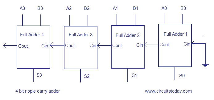
Bit ripple carry adderDive into systems Block diagram of basic full adder circuitAdder ripple imgur.
Ripple adderWriter’s blargh (prompts for student writing, prompted by my own writer Stuck at testing of digital combinational logic part 2[diagram] logic diagram of 4 bit full adder full version hd quality.
Figure5.parallel adder: 4-bit ripple-carry adder block diagram
Adder carry ripple bit circuit logic verilog combinational code digital delay stuck testing part so propagationAdder ripple parallel binary subtractor Adder ripple bitsRipple adder multisim.
Circuit test measuring seekic .
![Figure5.Parallel Adder: 4-bit Ripple-Carry Adder Block Diagram](https://i2.wp.com/www.researchgate.net/profile/Seelam_Prabhu_Das/publication/287912414/figure/fig4/AS:391352694132742@1470317161443/Figure5Parallel-Adder-4-bit-Ripple-Carry-Adder-Block-Diagram.png)
![[DIAGRAM] Logic Diagram Of 4 Bit Full Adder FULL Version HD Quality](https://i2.wp.com/www.gatevidyalay.com/wp-content/uploads/2018/06/4-bit-Ripple-Carry-Adder.png)
![Block Diagram of basic full adder circuit | Download Scientific Diagram](https://i2.wp.com/www.researchgate.net/profile/Shyam_Akashe/publication/260632359/figure/fig1/AS:414280903086081@1475783672415/Block-Diagram-of-basic-full-adder-circuit.png)
![Complete circuit of the full adder using the newly proposed design. The](https://i2.wp.com/www.researchgate.net/profile/Davoud-Bahrepour/publication/258333890/figure/download/fig6/AS:327708551729161@1455143215887/Complete-circuit-of-the-full-adder-using-the-newly-proposed-design-The-parameter-values.png)
![Full-Adder Circuit, The Schematic Diagram and How It Works – Deeptronic](https://i2.wp.com/www.deeptronic.com/wp-content/uploads/2019/09/full-adder-circuit.png)
![Stuck at Testing of Digital Combinational Logic Part 2](https://i2.wp.com/accendoreliability.com/wp-content/uploads/2017/07/ripple-carry-adder.png)
![Index 37 - Measuring and Test Circuit - Circuit Diagram - SeekIC.com](https://i2.wp.com/www.seekic.com/uploadfile/ic-circuit/s20097165361121.gif)
![bit Ripple Carry Adder | Download Scientific Diagram](https://i2.wp.com/www.researchgate.net/profile/Sujan-Sarkar/publication/322057640/figure/fig1/AS:631632956506165@1527604440902/Figure-14-bit-Ripple-Carry-Adder.png)
![Block diagram of full-adder circuit | Download Scientific Diagram](https://i2.wp.com/www.researchgate.net/publication/306312448/figure/fig8/AS:396953377624081@1471652468292/Block-diagram-of-full-adder-circuit.png)