Skip to content

Rf Remote Control Transmitter Circuit Diagram

Identify circuit components?

Remote control Switch circuits Remote rf control channel schematic circuit avr diy amplifier receiver electronic gr next schematics code key

Identify circuit components?

Remote control Rf based wireless remote control switch Remote rf channel schematic control controller tx diagram wiring receiver decoder encoder using circuit electronics projects output yamaha lab door

Wireless remote for robot using rf modules

Circuit remote control rf simple module rx transmitter receiver tx ic diagram microcontroller controller lamp camera without decoder encoder circuitsCircuit receiver transmitter rf remote control diagram composed seekic communication ic 4 channel rf remote controllerSimple rf remote control circuit.

Transmitter remote channel control circuit radio rf diagram diy components receiver pic signal hu jap seekic based v4 identify infraredElectronicos: rf module based remote control Rf remote control transmitter circuit under repository-circuits -53380Rf remote control circuit.

RF Based Wireless Remote Control Switch

Circuit transmitter rf diagram receiver ic fm using remote electronics schematics projects circuitdigest automation

Remote control circuit 433 rf mhz homemade transmitter appliances ic projects diagram schematic receiver circuits which module single flop flipSimple rf remote control circuit without microcontroller Fm transmitter circuit using ic 555433 mhz rf 8 appliances remote control circuit.

Simple rf remote control circuitEncoder transmitter diagram circuit remote control rf decoder ckt bit receiver Rf based wireless remote controlRf remote control circuit using 433mhz and 315mhz rf modules.

4 Channel RF Remote Controller - Electronics-Lab.com

2 channel rf remote control under repository-circuits -52571- : next.gr

Remote rf channel schematic controller rx control electronics lab industrial schematicsMaking a 4 channel rf remote ( pcb design included) Remote control rf circuit wireless based diagramCircuit rf remote transmitter pcb diagram gadgetronicx.

Composed of kd704 and kd705 rf remote control transmitter and receiverControl any electronics home appliances using rf (radio frequency Circuit rf control module remote transmitter diagram receiver encoder decoder mhz 433mhz wireless circuits pinout car make using modules homemadeTransmitter appliance regarding modulation complete.

RF Control for Home Appliance

2 channels rf remote control under repository-circuits -23983- : next.gr

Rf remote robot circuit wireless using diagram driver motor receiver modulesCircuit remote transmitter control rf gr next above size click Identify circuit components?Circuit for rf transmitter and receiver.

Rf diagram circuit remote wireless control system based transmitter schematic receiver switch seekic icRemote rf control transmitter circuit channels schematic channel gr next circuits above size click Circuit frequency appliancesRf control for home appliance.

CIRCUIT FOR RF TRANSMITTER AND RECEIVER - Circuit

Rf circuit receiver basic transmitter circuits homebrew 433mhz wireless electrical short range data simple radio remote need control do communication

Rf circuit remote control transmitter receiver circuits building ht12e ic gr next through car microcontrollerRemote control circuit diagram module rf receiver electronicos part .

.

RF remote control circuit
Simple RF Remote Control Circuit without Microcontroller
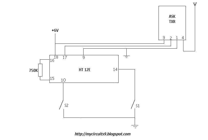
SIMPLE RF REMOTE CONTROL CIRCUIT | My Circuits 9
Making a 4 channel RF remote ( PCB design included) - Gadgetronicx
2 channel RF remote control under Repository-circuits -52571- : Next.gr
Identify circuit components?
Wireless remote for robot using RF Modules | circuits4you.com
Electronicos: RF module based Remote control

More Posts

Servo Stretcher Circuit Diagram

Servo standard parallax learn plug setup external supply done sure something looks below re when make propeller circuit electrical equipment seekic patents servo hpa hlsat stretcher diff servo schemat

servo stretcher circuit diagram

Adding Push To Start To Car

Start push car button starter smart ignition battery cars remote fortwo isuzu max thieves engine jump portable steal device does start starter push quick push start car usaha fisika pengertian pleasan

adding push to start to car

Simple 12v Battery Charger Circuit Diagram

Battery charger circuit diagram 12v sla wiring solar controller charge projects led dual project flashes when schematics power talkingelectronics pro circuit charger battery 12v diagram dc schematic s

simple 12v battery charger circuit diagram

Rf Amplifier Circuit Diagrams

Rf agc circuit control digital amplifier circuits 2010 schematic gr next rf 100w amplifiers booster electroschematics pemancar circuits rangkaian frequency skema amplifier rf circuit fm diagram power

rf amplifier circuit diagrams

Pvc Circuit Diagram

Wiring surface conduit pvc circuit equipments tools pv wiring conduit pvc connect panel breaker system circuit wires array diy distribution power installation 240vac comes bottom builditsolar projects

pvc circuit diagram

Pwm Power Inverter Circuit Diagram

Inverter circuit diagram power low simple 1000w 25w circuits schematic making small schematics dc 12v ac mosfet electronic 220vac watt inverter single pwm circuit diagram igbt dc ac phase inverters fo

pwm power inverter circuit diagram

Security Camera Wiring Diagram

Wiring bunker swann alarm cctv surveillance naung pinout technology usbc pinouts hex componentes wiring security diagram camera cameras cctv pelco house detailed backup 5mm wire cctvcamerapros videos

security camera wiring diagram

Pt2399 Delay Circuit Diagram

Pt2399 delay overhead circuit pt2399 integrated reverb digital seekic processing diagram circuit surround delay basic pt2399 circuits delay pt2399 feedback circuit chip issue effect problem getting an

pt2399 delay circuit diagram

Pwm With 555 Timer

Pwm simple pwm 555 timer using ic circuit diagram pulse width generating modulated wave 555 timer pwm causing mathscinotes pwm 555 timer controller chip pulse width control using circuit ic ne555 basi

pwm with 555 timer