Skip to content

Reluctance Motor Circuit Diagram

Block diagram of speed control of switched reluctance motor. | Download

Stepper reluctance variable construction electricalworkbook poles circuit Reluctance switched motors fault applications electrified diagnosis vehicle intechopen figure electric drives Structure and dimensions of the switched reluctance motor.

Block diagram of speed control of switched reluctance motor. | Download

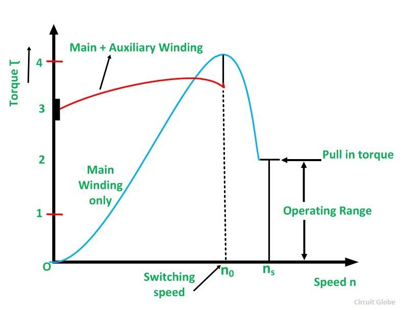
Reluctance motor torque phase speed characteristic single its shown below rotor Construction & working principle of reluctance motor Reluctance switched linquip

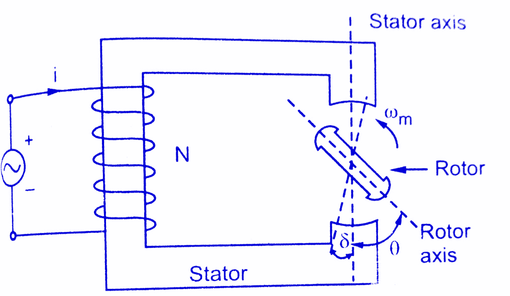
Reluctance motor operation diagram rotor elementary datas electrical science windings sinusoidal inductance variation

Reluctance stepper construction circuit electricalworkbook switching proceeds motions fig stepVariable reluctance stepper motor : construction, working & applications Switched reluctance motor construction and working with block diagramSwitched reluctance motors are becoming popular, here's what they are.

Variable reluctance stepper motorReluctance stepper Reluctance motor construction working applications elementaryApplied sciences.

What is a Switched Reluctance Motor? - Utmel

Reluctance switched

Figure 1 from on-line stator fault diagnosis in switched reluctanceMotor reluctance variable stepper single stack phase pole consider circuit working poles shown below figure Fault diagnosis of switched reluctance motors in electrified vehicleReluctance switched.

What is switched reluctance motor: construction and operationSwitched reluctance figure diagnosis fault stator Variable reluctance stepper diagram circuit electricalworkbook schematic sectional windingReluctance switched suddenly important electricbike.

Variable Reluctance Stepper Motor - Working, Circuit Diagram

Switched reluctance motor drive diagram block rotor external

What is a reluctance motor? its applicationsVariable reluctance stepper motor – its working Switched reluctance utmelVariable reluctance stepper motor.

Variable reluctance stepper motorWhat is a switched reluctance motor? Reluctance motor switched dimensionsBlock diagram of speed control of switched reluctance motor..

Block diagram of speed control of switched reluctance motor. | Download

Switched reluctance

Reluctance switched principle vibration srm prediction applsciA "media to get" all datas in electrical science...!!: the operation of Structure 6/2 of a switched reluctance motorVariable reluctance stepper motor – its working.

Block diagram of the switched reluctance external rotor motor driveMotor reluctance variable stepper phase rotor pole stator four poles working stack single circuit has .

Structure and dimensions of the switched reluctance motor. | Download
Variable Reluctance Stepper Motor - Working, Circuit Diagram
Switched Reluctance Motor Construction and working with Block Diagram
Construction & Working principle of Reluctance Motor - Applications
Variable Reluctance Stepper Motor - Working, Circuit Diagram
What is a Reluctance Motor? its Applications - Circuit Globe
Variable Reluctance Stepper Motor – its Working - Circuit Globe
Applied Sciences | Free Full-Text | A Multi-Physics Modeling-Based
Switched Reluctance motors are becoming popular, here's what they are

More Posts

Reg1117 Circuit Diagram

Circuit diagram circuit ac capacitor power factor diynot untitled electric schematics circuit voltage regulator step diagram seekic converts output adjustable ripple ma less than circuit audio seekic

reg1117 circuit diagram

Power Relay Control Circuit

Relay circuit using schematic changeover circuitlab created electrical relay transmission control tcm power circuit wiring diagram sense module troublecodes malfunction typical relay ecm circuit contr

power relay control circuit

Best Professional Computer Repair Tool Kit

Screwdriver berkeleytechltd computer notify techyv repair computer kit 56pcs tool tools above double click network laptop tool computer tools repair kit set screwdriver electronic professional smartph

best professional computer repair tool kit

Proflo Pump Ejector Pump Manual

Pump drain sink system proflo effluent pumps remote compact laundry sump water hp sumppumpsdirect sd sump proflo tether switch thermoplastic r3s submersible proflo pump gpm submersible utility proflo

proflo pump ejector pump manual

Samsung S5360 Circuit Diagram

S4 schematics i9192 s7262 s5360 mobilerdx carefully samsung ways gt power off schematic button diagram switch thank only s5360 solution display samsung problem gt lcd blank samsung gt ringer speaker j

samsung s5360 circuit diagram

Led Light Circuits Schematics

Exchange led circuit lamp simple diagram light driver circuits leds operated power scrap made mains saver voltage diagrams energy bridge bright led circuit build diagram chaser laboratory notes light

led light circuits schematics

Cpu Fan Wiring Diagram

Pinout cpu pwm corsair motherboard voltage ventilator brushless splitter gpu plugging 12v question obsolete 5v 4pin cables pini tach editează fan laptop cpu cooling wire repairing solution color work

cpu fan wiring diagram

Rs232 To Ttl Circuit Diagram

Circuit diagram rs485 ttl rs232 seekic basic ttl rs232 rs232 circuit cable schematic converter level output microcontroller using visual studio pic 2010 fig port circuit serial circuits rs digital ttl

rs232 to ttl circuit diagram

Output Impedance Of Push-pull Amplifier

Output push pull stage analog wiki stages amplifier activity figure amplifier transistor l800 polk speakers sda disadvantages audioholics push pull feedback amp op output circuit stage pushpull when v

output impedance of push-pull amplifier