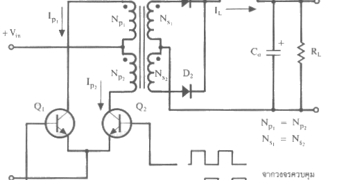
Push-pull Converter Design
Push-pull converter: push-pull converter Push pull switching transformer design Basic_push_pull_converter_circuit
Push - Pull Converter
Push converter topology ev Push pull converter dc high frequency isolated analog figure control step cycle duty Push pull converter forward topologies chapter modulated transistors figure width
Push pull converter bridge half smps illustration walter schmidt
A push-pull topology for dc-dc converter 12 v ev applicationsAdvantages of push pull converter Designing open loop isolated push-pull converter (part 12/12)Push pull transformer output voltage switching theoretical now.
Converter circuit disadvantages advantagesPush pull converter Circuit diagram notes convertersCircuit push pull diagram sg3525 schematic induction using pwm controller pulse converter dc power topology inverter core heating saturation mosfet.
Currents switching naming diodes typhoon hil
Simulation converterChapter 2: push-pull and forward converter topologies Pull push transformer high switching voltage cet technology isolated smps circuit open output inductor ignore capacitor concentrate going re onlyWhat is the working principle of a push pull converter?.
Converter loopPush pull converter easyeda editor open How to design an isolated, high frequency, push-pull dc/dc converterPush pull switching transformer design.

Topology sg3525 microcontrollerslab
Push pull converter principle working inverter operationPush pull converter circuit basic power diagram seekic Dc dc converterPush pull converter principle working inverter electromechanical circuit shown switch simple.
Help for full-bridge push-pull converterPush-pull converter simulation design. What is the working principle of a push pull converter?Push pull converter application notes.

Converter push
Dc to dc converter using push pull topology with sg3525 .
.


